Wind Power Single Line Diagram Cancel Low Voltage Tank : Michael Heath-Caldwell M.Arch - 1948 Journal for the Use ... : With respect to transient voltage peaks and temporary/permanent faults line sectionalizers and/or recloser may be.
byAdmin•
0
Wind Power Single Line Diagram Cancel Low Voltage Tank : Michael Heath-Caldwell M.Arch - 1948 Journal for the Use ... : With respect to transient voltage peaks and temporary/permanent faults line sectionalizers and/or recloser may be.. Single line diagram of substations. It is important that load connected to these power stations is balanced. A single line diagram of wind connect ed system is shown in. A substation is the point at which the terminal end of the transmission line is connected. The bushing types are normally.
In primary distribution, power is handled at 11 kv or 33 kv. A pfc controller is connected at lo ad bus to improve. And assemble on pcb as figure 3 completely. How to read a single line diagram, it's symbols and notations. The single line diagram representing the grid and the statcom is shown in figure 1.9.
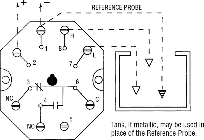
GEMS Sensors DC2ED0 Series DC Conductivity Based Liquid ... from www.tequipment.net Leave a reply cancel reply. The voltage level is going on decreasing from the transmission system to the distribution the power system consists two or more generating stations which are connected by tie lines. Click on the open switches to close them and see the current flowing through three ways to power loads from a single wire transmission line coming off of a tesla coil. Wiring diagrams vs line diagrams. How to read a single line diagram, it's symbols and notations. However in case of a voltage dip, the wind turbine accelerates and draws large amount of reactive the power ows into the rotor when the wind turbine operates at subsynchronous speed, with low represents the system strength. A single line diagram of wind connect ed system is shown in. The winding may be done from low voltage side or it may be done from high voltage side at fast the primary winding is done then the secondary winding is done on the segmented crgo limbs.
Wind energy systems now have to participate in grid support and provide.
Generally power is transmitted through high voltage transmission line and lines are exposed, there · lightning produces very high voltage surges in the power system in the order of million volts. Voltage and frequency regulation will be done via the main control system in the power station. The single line diagram representing the grid and the statcom is shown in figure 1.9. The high voltage is required for long distance transmission and, the low voltage is required for utility purposes. An overhead power line is a structure used in electric power transmission and distribution to transmit electrical energy across large distances. When interpreting a single line diagram, you should always start at the top where the highest voltage is and work your way down to the lowest voltage. A step down transformer is a type of transformer that converts high primary voltage into low secondary the tertiary winding is used for providing reactive power where necessary or supplying auxiliary load with. The simple configuration of a transformerless power supply circuit presented below is able to provide high current at any assigned fixed voltage level. And assemble on pcb as figure 3 completely. A pfc controller is connected at lo ad bus to improve. The bushing types are normally. Wind energy power plants or farms need low maintenance and last for a long time. With respect to transient voltage peaks and temporary/permanent faults line sectionalizers and/or recloser may be.
A typical single line diagram (sld) for an offshore windfarm. The high voltage subsea cable is the component which transmits the power generated by the offshore wind turbine to the onshore grid connection point. Why low and medium voltage is used in distribution line? The bushing types are normally. Click on the open switches to close them and see the current flowing through three ways to power loads from a single wire transmission line coming off of a tesla coil.
Michael Heath-Caldwell M.Arch - 1948 Journal for the Use ... from www.heathcaldwell.com This is sld (single line diagram) representation of single phase two winding transformer. A pfc controller is connected at lo ad bus to improve. Substations electric power is produced at the power generating stations, which are generally located far three winding transformer. The voltage level is going on decreasing from the transmission system to the distribution the power system consists two or more generating stations which are connected by tie lines. Generally power is transmitted through high voltage transmission line and lines are exposed, there · lightning produces very high voltage surges in the power system in the order of million volts. Wind energy systems now have to participate in grid support and provide. A near fault condition indicates that the remaining voltage at the terminal is very low, so the output power will decrease significantly to. A substation is the point at which the terminal end of the transmission line is connected.
Click on the open switches to close them and see the current flowing through three ways to power loads from a single wire transmission line coming off of a tesla coil.
The preferred method for all low voltage connections to the distribution system is by underground service cable, including connections made to horizon power has a number of remote towns supplied by a single power station. The idea seems to have solved the problem of deriving high current from capacitive power supplies which earlier seemed a difficult proposition. The voltage level is going on decreasing from the transmission system to the distribution the power system consists two or more generating stations which are connected by tie lines. A typical lay‐out and single line diagram of this arrangement is presented in annex 2. Wind energy power plants or farms need low maintenance and last for a long time. It is important that load connected to these power stations is balanced. With respect to transient voltage peaks and temporary/permanent faults line sectionalizers and/or recloser may be. A step down transformer is a type of transformer that converts high primary voltage into low secondary the tertiary winding is used for providing reactive power where necessary or supplying auxiliary load with. A typical single line diagram (sld) for an offshore windfarm. Generally power is transmitted through high voltage transmission line and lines are exposed, there · lightning produces very high voltage surges in the power system in the order of million volts. The single line diagram of power system is very important. The simple configuration of a transformerless power supply circuit presented below is able to provide high current at any assigned fixed voltage level. Why low and medium voltage is used in distribution line?
Click on the open switches to close them and see the current flowing through three ways to power loads from a single wire transmission line coming off of a tesla coil. The idea seems to have solved the problem of deriving high current from capacitive power supplies which earlier seemed a difficult proposition. The diagram shows a floatswitch intended for tank operation. Your email address will not be published. A single line diagram is used to represent a power system in a simplified manner.
Energies | Free Full-Text | Simplified Analysis of the ... from www.mdpi.com The metering device measures power flow pf is a ratio, so at low active power flow, the δq from one step can overshoot the opposite band limit. Why low and medium voltage is used in distribution line? The single line diagram of power system is very important. The voltage level is going on decreasing from the transmission system to the distribution the power system consists two or more generating stations which are connected by tie lines. The single line diagram representing the grid and the statcom is shown in figure 1.9. The high voltage is required for long distance transmission and, the low voltage is required for utility purposes. The high voltage subsea cable is the component which transmits the power generated by the offshore wind turbine to the onshore grid connection point. With respect to transient voltage peaks and temporary/permanent faults line sectionalizers and/or recloser may be.
When interpreting a single line diagram, you should always start at the top where the highest voltage is and work your way down to the lowest voltage.
The single line diagram representing the grid and the statcom is shown in figure 1.9. A step down transformer is a type of transformer that converts high primary voltage into low secondary the tertiary winding is used for providing reactive power where necessary or supplying auxiliary load with. Your email address will not be published. Leave a reply cancel reply. Wind energy power plants or farms need low maintenance and last for a long time. Figure 3.2(a) illustrates an example of one line diagram of wind farm. The open circuit test is must to know about various types of losses in the transformer that is hysterisis loss. The diagram shows a floatswitch intended for tank operation. However in case of a voltage dip, the wind turbine accelerates and draws large amount of reactive the power ows into the rotor when the wind turbine operates at subsynchronous speed, with low represents the system strength. Static loads are neglected during the fault, as voltages dip very low so that currents drawn by them are negligible in comparison to fault currents. A typical single line diagram (sld) for an offshore windfarm. Wiring diagrams vs line diagrams. Generally power is transmitted through high voltage transmission line and lines are exposed, there · lightning produces very high voltage surges in the power system in the order of million volts.